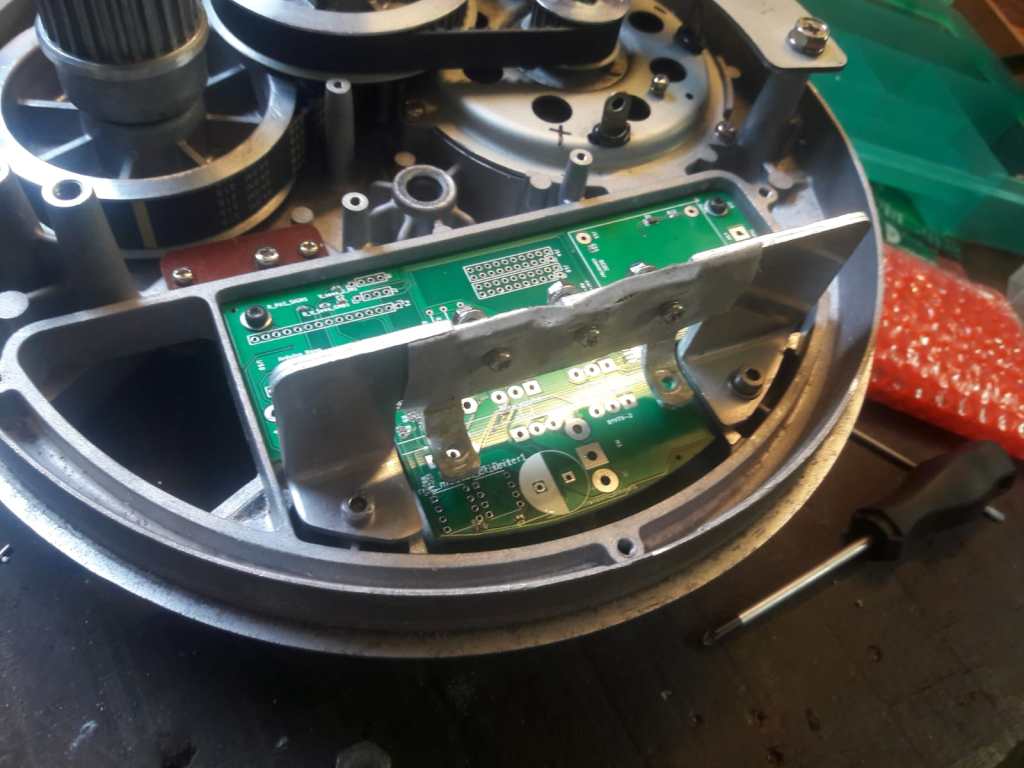
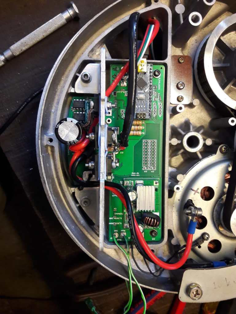
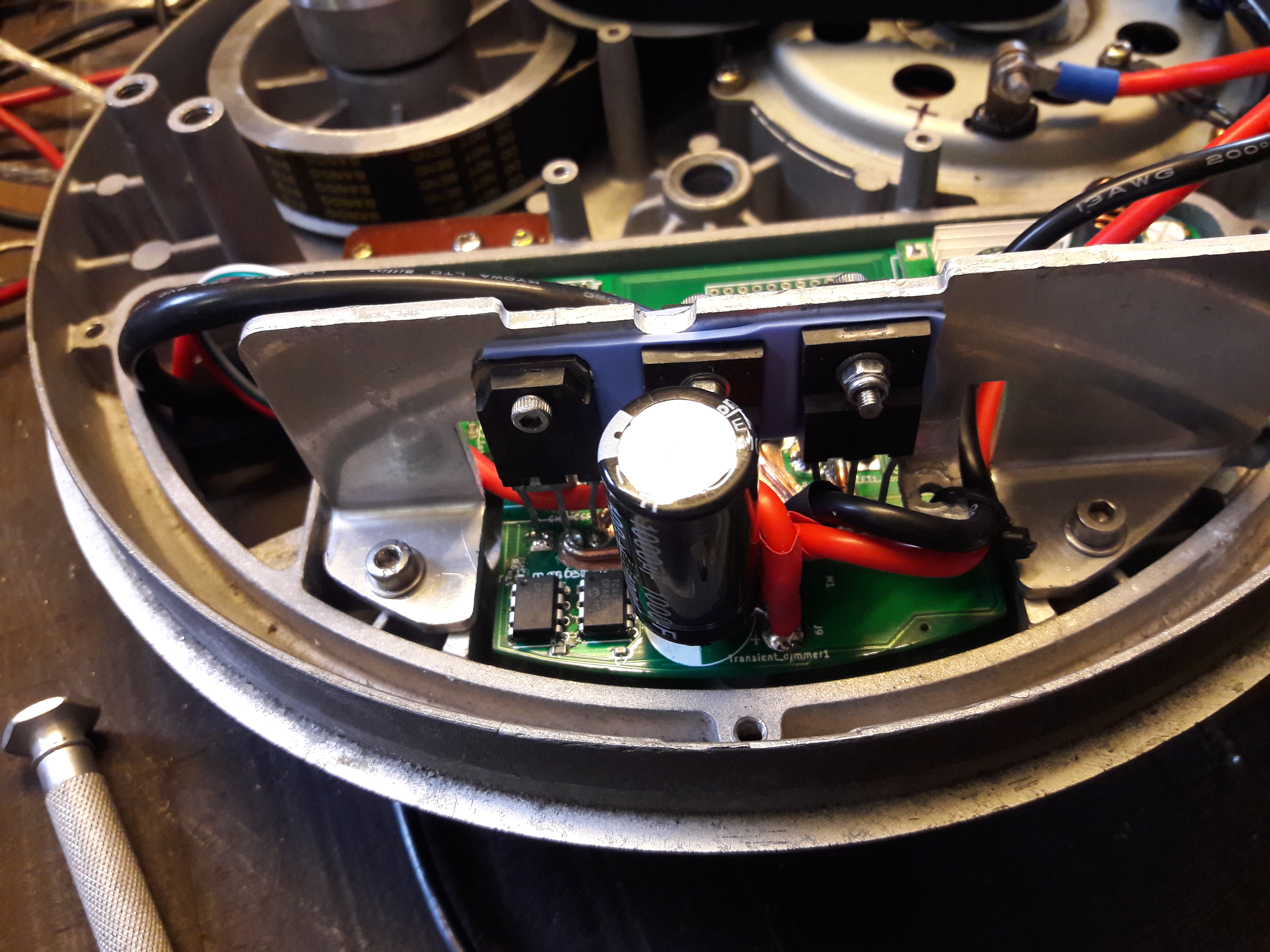
After trying out different configurations, I have designed a final PCB to finish it into a hopefully reliable build. I decided to use two larger-than-original parallel transistors for the PWM switching, and two diodes to dampen voltage peaks by leaking to either ground or battery. I also employ a large capacitor to dampen voltage ripple.
I noticed that the original design uses the two transistor in series, rather than in parallel. Perhaps this is done out of safety considerations: When one of the transistors fails, the other still prevents the motor to be in a permanent ON state.
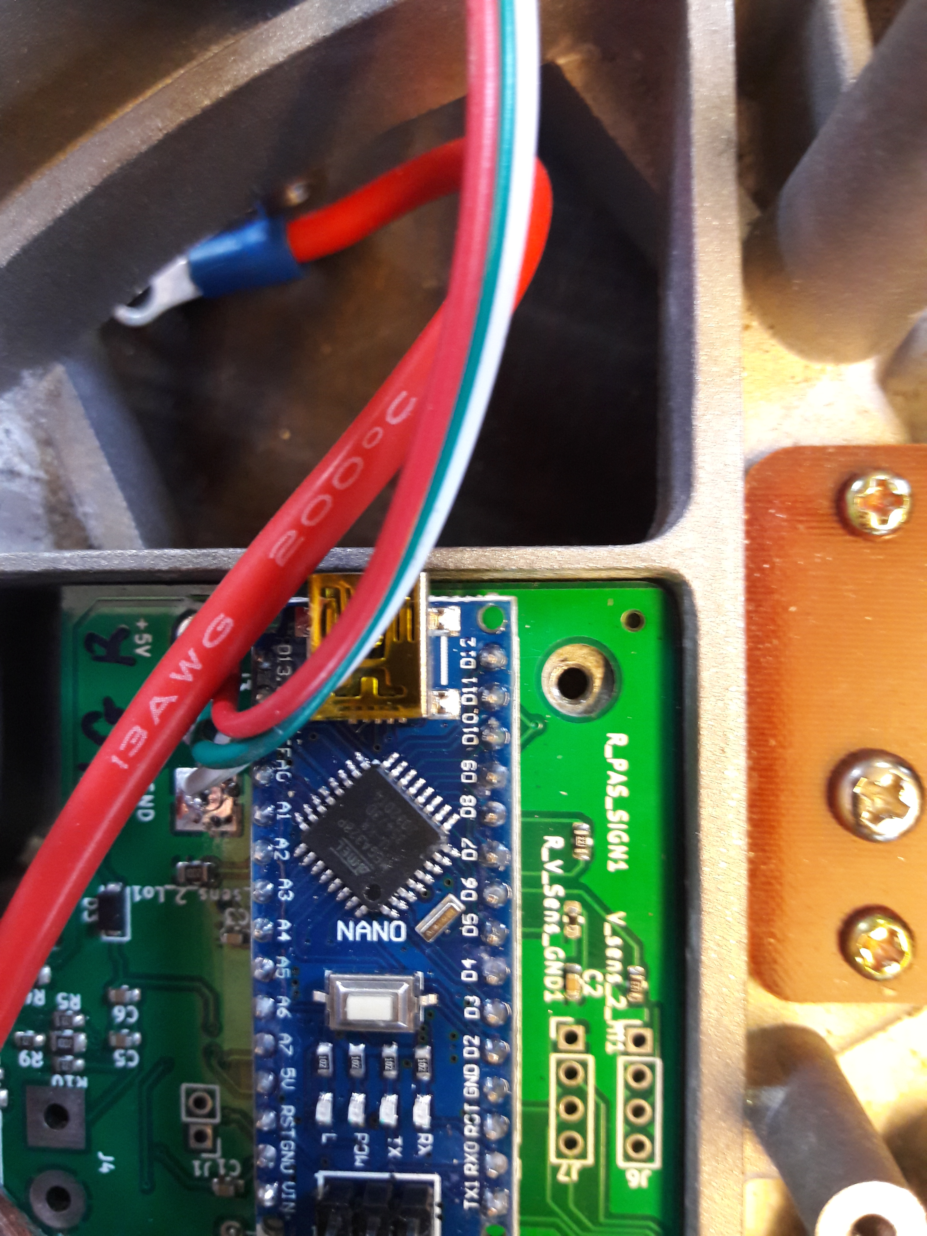
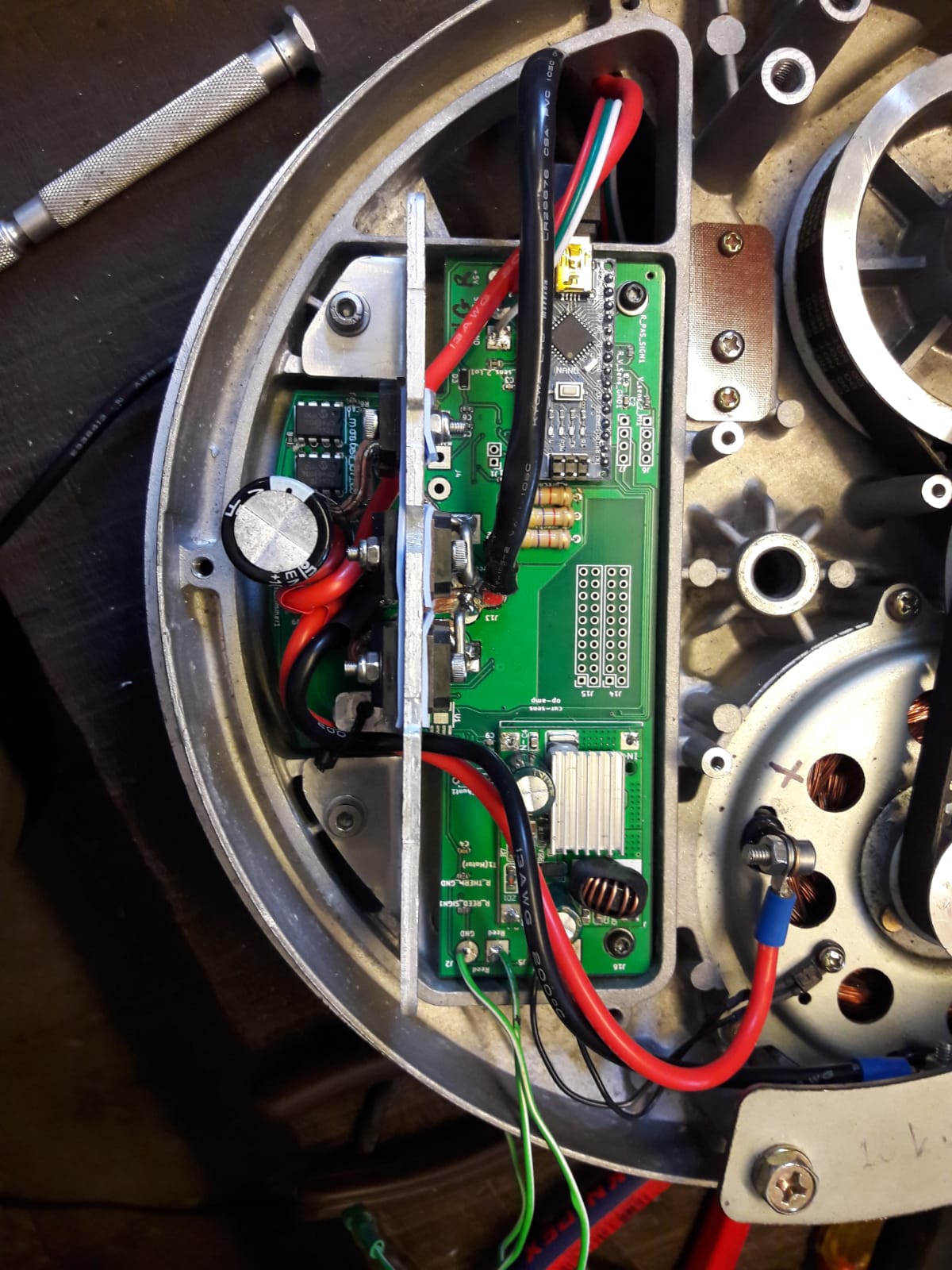
Since I was afraid of overheating of the power traces on the PCB, I scratched the top surface to expose the copper, and added a solid copper wire on top of them and soldered them on. As you might see, I have re-used the current shunts. I have left space for an op-amp for the possible current measurement in the future, but I haven’t actually installed it since it doesn’t seem necessary for a decent riding experience. Ideally, I would try to take the time to work with the torque sensor, and get rid of the PAS sensor, but I have too many other projects that I prioritize at the moment.

About the torque sensor
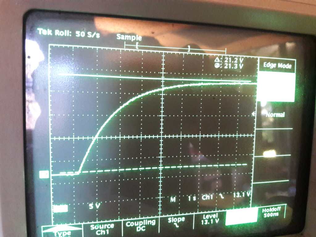
I have left space for electronics for the readout of the torque sensor, although so far I have not attempted to use it. Just out of curiosity, I have diagnosed the readout scheme of an original running CMU-3 hub (the one with three internal gears). To my surprise, the PWM frequency of the DC motor drive was set at only 300 Hz (I thought this was typically much higher, and I am driving it at a PWM frequency of about 3 kHz). The torque readout was done at a much higher frequency of about 4kHz. I suspect that the Sanyo software is written such that the torque readout is done separate in time from the PWM switching events.
Motor temperature
Since I have increased the battery voltage from 24 to 48 volts, the motor delivers about 4 times the power, and temperature management can become an issue. Sanyo has built in a thermistor at the motor, and I read it out to determine if the motor should run at half the PWM duty cycle. During use I have encountered a few times that the motor would become warm and fall into this ‘limp home’ mode (for example when I the road ascends over a longer stretch and the outside temperature is high).
BMS and Battery drama
The BMS of the battery attached to this motor has failed on me, causing the battery to slowly deplete. One day I found this 48V Li-ion battery at only a few Volts (!!!!). I was pretty sure I wasted a new battery, but after very slowly charging it using a bench power supply, it came back to life. Increasing the voltage went very fast up to 30 Volts or so, after that the battery took more current and the voltage increase slowed down. I still reach a range of more than 40 km with this battery (78 cells, 13S6P Panasonic NCR18650B 3250mAh – 6.7A). I did notice that the battery voltage dropped much quicker than a healthy battery would, so I programmed in that the PWM duty cycle would decrease when a certain low voltage threshold was reached. This works fine in practice. In short: you can be lucky and bring an an almost-at-0V battery back to life, but not to the original state. Better than nothing!
Final use
I have used the bikes a few times for daily commuting. I have limited the PWM duty cycle to be 70 percent at the most, since that is what I am comfortable with in normal traffic. If I would drive the motor at full ON state, the motor would supply too much power, and also overheat. Reflecting on the battery choice, I think a 36V battery would have been more suitable for this build.
PCB schematics download
Unfortunately I am not allowed to share the entire KiCAD file, but feel free to contact me to ask for the full files.
Arduino software
The software is pretty quick-and-dirty, so bear with me … 🙂

Leave a comment