Since I have received the question whether I could supply the designed PCB (described here), I have decided to write more elaborately what I have modified to build the PCB into the hub.
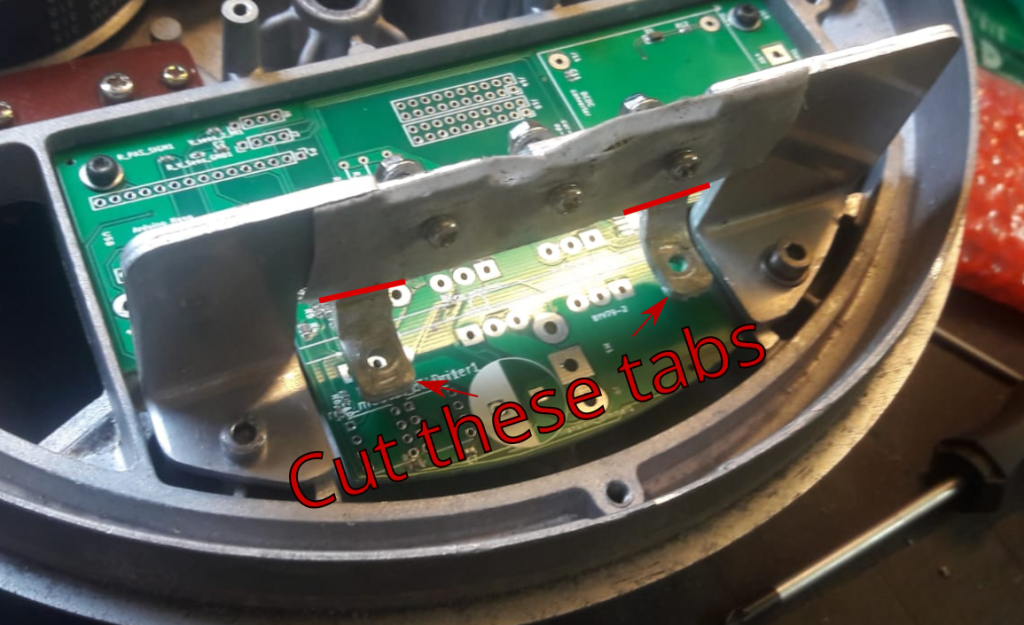
You should cut the tabs that are originally used for the mounting of the PCB: there will be a diode and extra transistor mounted there, so you need to make space. You will also need to drill holes to mount the diode and transistor.
You can certainly run this motor at different battery voltages! I have decided for 48 Volt, but in retrospect 36 Volt would have been more appropriate. 24 Volt (like the original) is thus of course also possible. In the arduino software, just indicate what the amount of lithium cells are, and the upper and lower voltage limits will be taken into account. Note that you should always calibrate the voltage sensing resistors, as they are their accuracy is usually +/- 5%. You should do this in the function ‘Read_battery_voltage’, where you can set the resistor value of the two voltage reduction resistors. I recommend tuning it on the measured voltage, not on the measured resistance. The Arduino code I used is attached at the end.
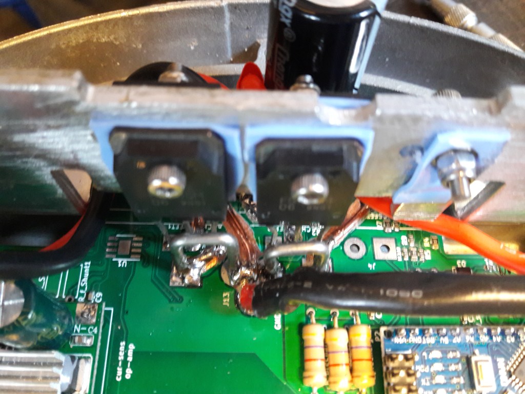
I have used two n-ch mosfets in parallel. However, if you are using this module at 24 Volt (or perhaps even at 36 Volt), you might be able to use only one transistor. I have never done a proper load test, so I cannot guarantee success.
Before soldering on the components, I have scratched off the top conductive layer of the PCB, and then laid some tin solder (and a solid electrical wire) on top. I did this to prevent channels to burn through, although this might in practice never happen (did not want to risk it).
Sensors
As mentioned in the previous post, I do not use the induction (torque) sensor built into the CMU-1. I have also disabled the small rotation between sprocket side and wheel (the movement used to measure the torque with). I found this movement quite annoying, as it seems to take away part of the power pedal stroke. So instead, I have used an external PAS pedal sensor.
I am still using the reed sensor as a speed indicator.
Shopping list:
If you are considering building this system into your hub, I would recommend buying the following components:
- Mini USB cable with 90 degree angle (recommended for better access). I ordered this one (down option).
- Heat conducting silicon pads, to mount the transistors and diodes (I ordered this one).
- Pedal PAS sensors (I ordered this one)
- n-channel MOSFET transistors (FS70SM)
- Arduino Nano (with micro USB connection)
- DC DC converter (I bought this one). I bought a separate unit, rather than a built-in SMD on the PCB. because I could not find a voltage regulator that could handle the voltage (up to 53 Volt) that Intended to use it with. At lower voltages (24-36V), you could move to a simpler voltage regulator chip.
- partly populated PCB: note that I have used a PCB with some SMD resistors and capacitors already installed. If you prefer to mount these components yourself, I share the BOM list (nano_ext_v1.xlsx).
- mosfet drivers (2x) TC4420 CPA.
- 2Watt resistors (3x) between 0.5-1kOhm (for capacitor pre-charging).
- Long M3 screws to mount the transistors and diodes.
- Large capacitor (I used 1mF) to suppress BUS fluctuations.
Skills required:
- Basic soldering skills
- Basic electronics knowledge
- Basic programming (arduino) knowledge.
Known issue 1: Battery charging:
I have to make sure that the battery is not connected to the motor when charging. This is probably because of voltage/current spikes induced by the charger. This then damages the 12V DC DC regulator, which then sends a too high voltage into the Arduino Nano. So, if you have suggestions to solve that issue, I would be happy to hear them. Right now, I charge the battery when ‘turning off’ the motor, and that works well.
Known issue 2: Overheating:
As mentioned in the earlier post, I have the issue of overheating the motor when running too long on a hot day. I would therefore again repeat that I recommend running the motor in combination with a 36V or 24V battery.
Some final notes
- For tuning and debugging, I print out some variables onto the Serial monitor screen in Arduino. The exported variables are defined in “print_drive_variables();” and ” print_safety_variables(); “.
- I have left the option to build in an operational amplifier, that is connected to a shunt (took out one that is originally built in the PCB). The more enthousiastic DIY-er could develop current-sensing and implement that into the control software, that would be a nice upgrade.
- As mentioned, the torque readout could be read out again, also a nice upgrade since it would imply running this motor without external sensors.

Leave a comment